- Full Adder Verilog Code
- 3 Bit Adder Verilog Code
- Four Bit Adder Verilog
- N Bit Adder Verilog
- 4 Bit Ripple Adder Verilog
Mealy Machine Verilog Code | Moore Machine Verilog Code
Full Adder Verilog Code

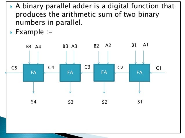
32 Verilog Mini Projects. Implementing 32 Verilog Mini Projects. 32 bit adder, Array Multiplier, Barrel Shifter, Binary Divider 16 by 8, Booth Multiplication, CRC Coding, Carry Select and Carry Look Ahead Adder, Carry Skip and Carry Save Adder, Complex Multiplier, Dice Game, FIFO, Fixed Point Adder and Subtractor, Fixed Point Multiplier and Divider, Floating Point IEEE 754 Addition Subtraction. Design a serial adder circuit using Verilog. The circuit should add two 8-bit numbers, A and B. The result should be stored back into the A register. Use the diagram below to guide you. Hint: Write one module to describe the datapath and a second module to describe the control. Design is a serial adder. It takes 8-bit inputs A and B and adds them in a serial fashion when the goinput is set to 1. The result of the operation is stored in a 9-bit sum register, The block diagram is attached. I am using Quartus II 13.0sp1 (64-bit) Web Edition. Serial Adder Moore Model Verilog - fasrwap VHDL code for an N-bit Serial Adder with Testbench code Normally an N-bit adder circuit is implemented using N parallel full adder circuits, simply connected next to each other. The advantage of this is that, the circuit is simple to design and purely combinatorial. 4 Bit Serial Adder Verilog Code For Full DOWNLOAD a1e5b628f3 4 Bit Ripple Carry Adder in Verilog. A,B); endmodule Structural Model: Full Adder module fulladder. I need 16-bit ripple carry adder testbench verilog code.4-bit Full Adder using Two 2-bit Full Adders. Unorthodox but I'm curious to know as I am new to Verilog.
This page covers Mealy Machine Verilog Code andMoore Machine Verilog Code.
Mealy Machine Verilog code
3 Bit Adder Verilog Code
Following is the figure and verilog code of Mealy Machine.
output out;
input in;
input clk, rst;
reg out;
reg[1:0] state;
parameters0=2'd0, s1=2'd1, s2=2'd2, s3=2'd3;
always @(posedge clk or negedge rst)
if(rst0) begin state=s0; out=0; end
else begin
case (state)
s0: if(in0) begin out=0; state=s1; end
else begin out=0; state=s0; end
s1: if(in0) beginout=0; state=s1; end
else begin out=0; state=s2; end
s2: if(in0) begin out=0; state=s3; end
else begin out=0; state=s0; end
s3: if(in0) begin out=0; state=s1; end
else begin out=1; state=s2; end
default: state=s0;
endcase
end
endmodule
Moore Machine Verilog code

Following is the figure and verilog code of Moore Machine.
output out;
input in;
input clk, rst;
reg out;
reg[1:0] state;
parameter s0=2'd0, s1=2'd1, s2=2'd2, s3=2'd3;
always @(posedge clk or negedge rst)
if(rst0) begin state=s0; out=0; end
else begin
case (state)
s0: begin out=0; if(in0) state=s1; else state=s0; end
s1: begin out=0; if(in0) state=s1; else state=s2; end
s2: begin out=0; if(in0) state=s3; else state=s0; end
s3: begin out=1; if(in0) state=s1; else state=s2; end
default: state=s0;
endcase
end
endmodule
Verilog source codes
Low Pass FIR Filter
Asynchronous FIFO design with verilog code
D FF without reset
D FF synchronous reset
1 bit 4 bit comparator
All Logic Gates
RF and Wireless tutorials
Four Bit Adder Verilog
Share this page
N Bit Adder Verilog
